![]()
![]()
![]()
![]()
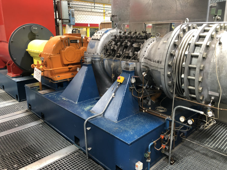
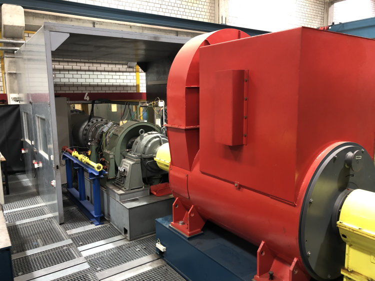
A three-phase synchronous motor with an output of Pel = 1,650 kW and infinitely variable speed adjustment up to N max = 1,500 rpm drives the axial compressor engaged in each case (switchable curved-tooth coupling, make Tacke). The drive power is transmitted to the axial compressors via a turbo spur gear (Tacke) and a planetary gear (BHS). The torque can be measured by means of a torque measuring shaft (manufactured by Hottinger-Baldwin). 3-stage axial and transonic medium-pressure compressor (type MTU) of an aircraft engine is installed on side AV 4-1 of the drive train. At a speed of N = 13,500 rpm, a mass flow of 13.4 kg/s and an overall pressure ratio П = 2.67 are achieved. Previous investigations on the compressor focused on transient flow effects in the region of the stability limit (rotating stall).On the opposite side AV 4-2 is a 4-stage axial compressor (type DEMAG) with complex adjustment mimics. This means that both the clocking position and thus the relative positioning of the guide vanes to each other over the circumference and the stagger angle of the tandem IGV and guide vane can be continuously adjusted. The total pressure ratio П of 1.8 and the mass flow of 13.6 kg/s were achieved at a speed N = 11,500 rpm. The focus of previous investigations was on the detection of transient flow effects at the grid boundaries with the aid of high-resolution measurement technology (e.g. piezoresistive pressure sensors and hot-wire probes).
Copyright © ttf 2023
Last update: Oct 02, 2023


