![]()
![]()
![]()
![]()
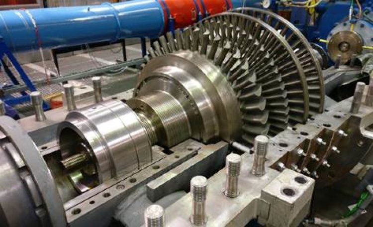
On this test rig, a 1-stage radial turbine (page RT 6-1) and a 4-stage axial turbine (page AT 6-2) are installed. The supply air for both turbines is provided by the gear compressor in pit 7. The axial turbine of industrial design (make MAN-GHH) is directly coupled to the eddy current brake (make Zoellner) via a torque measuring shaft and a curved tooth coupling. The brake serves as a load and to dissipate the turbine power. The turbine is designed for a total pressure ratio П= 2.7 at an inlet temperature of TE = 150° C, a speed N = 7,000 rpmand a throughput of 12.5 kg/s. The centripetal air turbine was specially designed for a research project and manufactured in the institute's own workshop. In contrast to the axial turbine, the coupling with the brake takes place in coordination with the brake map. The input speed of NRT,E of 24,000 rpm is therefore reduced to NRT,A = 7,000 rpm with the aid of a reduction gearbox (turbo spur gearbox, make Tacke). The radial turbine has an impeller with 13 blades and achieves an overall pressure ratio of П= 2.9.It was used mainly for flow studies of the spiral channel and upstream effects from the impeller. Optical as well as pneumatic measurement techniques were used to record velocity information in the single nozzle spiral of the turbine.
Speed:
Inlet temperature:
Inlet pressure:
Mass flow:
Power
Copyright © ttf 2023
Last update: Oct 02, 2023


